The Ultimate Guide to Mollar CGT20750 Skematik Drawing

Introduction to Mollar CGT20750 Skematik Drawing
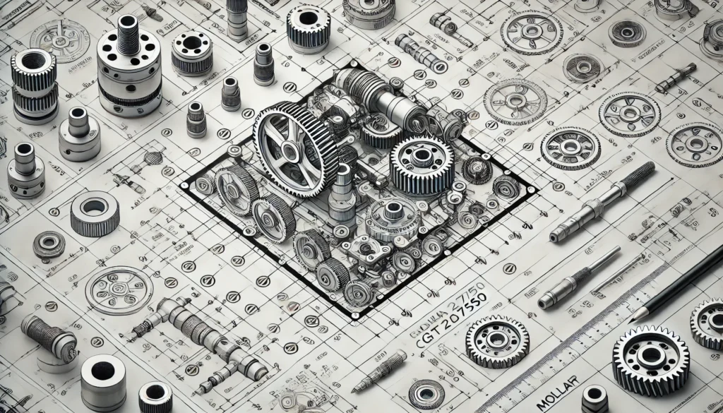
The Mollar CGT20750 skematik drawing represents a gold standard for technical schematics used in diverse industries like electrical, mechanical, and architectural design. These drawings are essential for creating accurate blueprints that bridge the gap between ideas and practical implementation. Whether you are designing an electrical circuit or drafting a machine prototype, Mollar CGT20750 ensures clarity, precision, and consistency.
This guide dives deep into the nuances of Mollar CGT20750 skematik drawing, offering step-by-step instructions, best practices, and advanced techniques to help professionals and enthusiasts alike create schematics that are both functional and visually impeccable.
Why Accurate Schematic Drawings Matter
Accurate schematic drawings are the backbone of successful engineering and design projects. Errors in schematics can lead to costly mistakes during manufacturing, delays in project timelines, and even safety hazards. Mollar CGT20750 drawings stand out by ensuring that every component, connection, and label is meticulously planned and executed.
For example, in the field of electrical engineering, a minor misplacement in a circuit drawing can result in malfunctioning systems or fire risks. Similarly, in construction, an inaccurate layout can compromise the structural integrity of a building. By adhering to Mollar CGT20750 standards, professionals can mitigate these risks and streamline their workflows.
Key Components of Mollar CGT20750 Skematik Drawing
Accurate Measurements and Scaling
Measurements and scaling are critical in schematic drawings. The Mollar CGT20750 standard emphasizes precision to ensure that every part fits perfectly in the final design.
For instance, in a mechanical blueprint, scaling discrepancies could render a part unusable. To maintain accuracy:
- Use software tools that offer automatic scaling features.
- Double-check measurements before finalizing the schematic.
Clear and Consistent Labeling
Labels act as the identifiers for various components within a schematic. They provide context and ensure that users can interpret the drawing without confusion. To follow Mollar CGT20750 guidelines:
- Label every component and connection clearly.
- Avoid overly complex labels; keep them concise yet informative.
Standardized Symbols
The Mollar CGT20750 standard utilizes a library of standardized symbols to represent various components. This ensures universal understanding and reduces the need for lengthy descriptions.
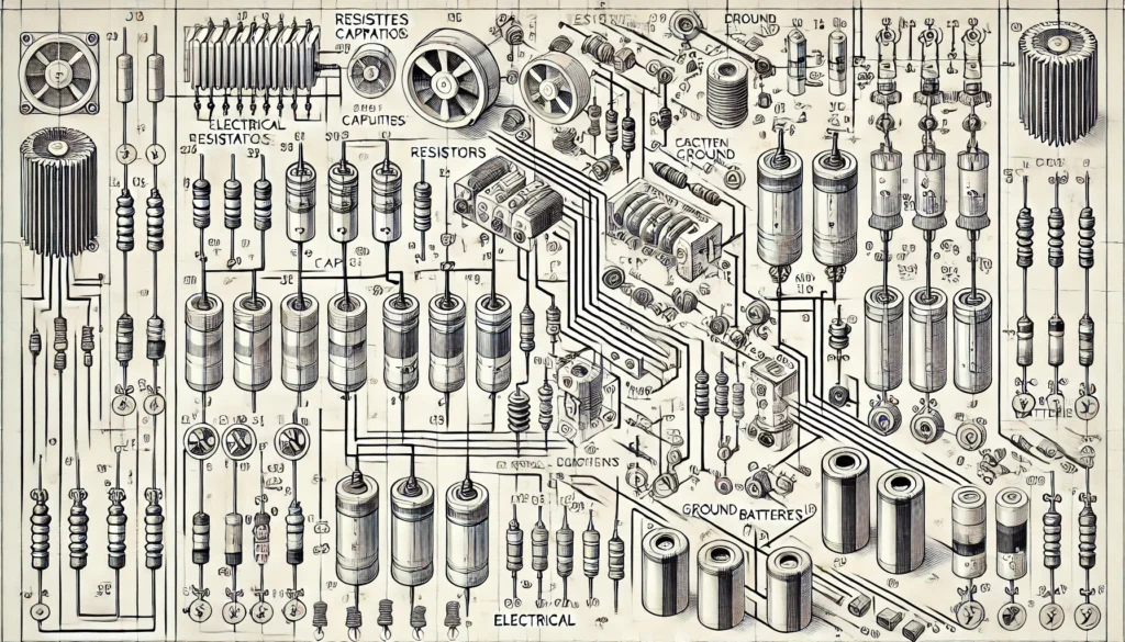
Here’s a sample table showcasing common symbols:
| Component | Symbol |
|---|---|
| Resistor | ⏐ |
| Capacitor | ⏔ |
| Electrical Ground | ⏠ |
| Battery | ⧗ |
Legends and Keys
Legends and keys are indispensable for decoding symbols and abbreviations in a schematic. A well-crafted legend aligns with Mollar CGT20750 standards by explaining each element succinctly.
Step-by-Step Guide to Creating a Mollar CGT20750 Skematik Drawing
- Pre-Planning: Gather all necessary information about the system, including specifications and requirements. A strong foundation minimizes revisions later.
- Select Software: Tools like AutoCAD, SolidWorks, and Visio are excellent for creating schematics that align with Mollar CGT20750.
- Draw Components: Begin by placing primary components on the canvas. Ensure that their orientation and spacing allow for clear connections.
- Connect Components: Use standardized lines and symbols to represent connections. Test the flow to identify potential issues.
- Add Labels and Legends: Ensure that all elements are labeled. Add a legend to explain uncommon symbols or terms.
- Review and Validate: Double-check the schematic for errors and inconsistencies. Engage a second pair of eyes for additional verification.
Applications of Mollar CGT20750 Skematik Drawing
Electrical Engineering
Mollar CGT20750 is widely used for circuit design, wiring diagrams, and power system layouts. It ensures safety and efficiency by visualizing the flow of electricity clearly.
Mechanical Engineering
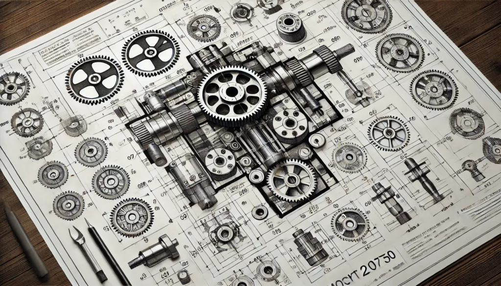
Machine designers rely on these drawings to create detailed blueprints that guide manufacturing. For example, a well-crafted Mollar CGT20750 schematic can help in prototyping and assembling complex machinery.
Construction and Architecture
From floor plans to HVAC systems, Mollar CGT20750 schematics enable architects and builders to align their designs with functional requirements.
Automotive Engineering
Automotive engineers use these schematics to design electrical systems, including battery circuits and lighting systems.
FAQs About Mollar CGT20750 Skematik Drawing
What software is best for Mollar CGT20750 schematics?
AutoCAD and SolidWorks are popular choices due to their precision and vast libraries of symbols.
How does Mollar CGT20750 compare to other standards?
Mollar CGT20750 prioritizes accuracy and readability, making it a preferred choice for technical professionals.
Can beginners learn to create Mollar CGT20750 schematics?
Yes, with the right resources and practice, beginners can quickly grasp the fundamentals.
Is there a specific guide for legends and symbols?
The Mollar CGT20750 standard includes a comprehensive library of symbols, which can be accessed via online resources or software plugins.
How do I ensure my schematics meet industry standards?
Regularly review your work against Mollar CGT20750 guidelines and consult industry references.
Conclusion
The Mollar CGT20750 skematik drawing is a cornerstone of modern engineering and design. Its emphasis on accuracy, clarity, and standardization ensures its relevance across industries. By mastering the techniques outlined in this guide, you can elevate the quality of your schematics, reduce errors, and foster seamless communication in your projects. Whether you are a beginner or a seasoned professional, adhering to these best practices will set you apart in the competitive world of technical design.
Additional FAQs for Mollar CGT20750 Skematik Drawing
How can I troubleshoot errors in my Mollar CGT20750 schematic drawing?
To troubleshoot errors, start by reviewing the schematic for common mistakes such as incorrect connections, mislabeled components, or missing legends. Use simulation software to test the functionality of your design before implementation. Peer reviews can also help identify overlooked issues.
Are there any certifications available for mastering Mollar CGT20750 schematics?
While there isn’t a certification specific to Mollar CGT20750, certifications in related fields like AutoCAD, SolidWorks, or electrical engineering often include schematic drawing training. These certifications can validate your expertise and enhance your professional profile.
What is the typical learning curve for mastering Mollar CGT20750 skematik drawing?
The learning curve depends on your familiarity with schematic design principles and related software. Beginners may take a few weeks to months of consistent practice, while experienced designers can adapt to the Mollar CGT20750 standard more quickly with the help of guidelines and tutorials.
Can Mollar CGT20750 schematics be converted to 3D models?
Yes, many advanced software tools allow users to convert 2D Mollar CGT20750 schematics into 3D models. This is particularly useful in industries like mechanical and automotive engineering for visualizing complex systems before production.
How do I update or revise an existing Mollar CGT20750 schematic?
Revisions should start with an audit of the current schematic to identify outdated elements or errors. Use version control software to manage changes systematically. Clearly mark updates in the schematic, such as using distinct colors or labels for new components, to ensure transparency during collaboration.
Recommended Articles:
From Replicability to Generalizability and Gulnoza: A Comprehensive Guide
Is 254-500-0535 a Scam? Uncovering the Truth Behind This Number
Can I Buy 1.5f8-p1uzt? The Ultimate Guide to Purchasing and Using 1.5f8-p1uzt
Emmyhii777: Guide to Following the Influencer Everyone’s Talking About
The Ultimate Guide to Mollar CGT20750 Skematik Drawing


